
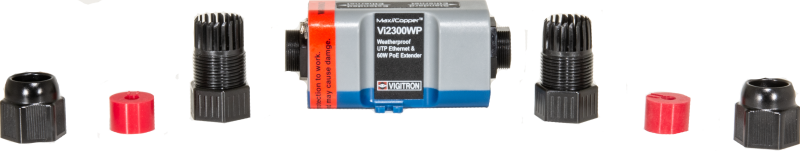


The VI-UTP-2300WP transmits 10/100Mbps Ethernet and PoE/PoE+ with UTP or Cat cable up to a distance of 500m. The Pass Through technology allows the PoE supply of e.g. a midspan to be passed on directly via UTP or Cat cable. The devices do not require any software configuration. The VI-UTP-2300WP is built into an IP67 protected housing and is therefore suitable for direct outdoor mounting without additional junction box.
More information
| System notes | Video assembly instructions The connection of several pairs of devices via the same cable can lead to transmission problems due to crosstalk between the different signals in the cable. Ideally, therefore, each device connection should be implemented using separate cables. If several cables have to be lined up along a connecting line, it is important to make these transitions as technically sound as possible. This means that ideally, professionally assembled RJ45 plugs are used for the transitions. If this is not possible, e.g. when using telephone cables, it is important to ensure that the stranding of the wire pairs is carried out as little as possible. The contact between the wires of the cables to be connected must be as good as possible galvanically. Shielded cables can cause problems due to potential equalisation currents. Especially when several cables are combined in one control panel, we do not recommend to use the shielding in the control panel to ground. |
Downloads
Applications

Technical data
General properties
| supply voltage | Power supply via PoE, the device cannot be powered locally. |
| MTBF | |
| operating temperature | -40 to +75°C |
| dimensions | 174x40x47mm |
| weight | 0,23kg |
interfaces
| copper ports | 1 x 10/100BaseT, RJ45 Please note the limited space for the RJ45 connectors. We recommend checking the compatibility of the RJ45 connectors before mounting in the field. |
| extender ports | 1 x RJ45, 2 or 4 pairs The unit cannot be powered locally. I.e. it cannot be used for pure data traffic via one pair. |
| transmission cable | Ideal type: Cat5e and better Other types: When using Cat3 cables (telephone cable) or bell wire, the possible distances are significantly reduced. When using Cat7 cables, you can expect approximately the same distances as with Cat5e/Cat6. The shields of the Cat7 cable must not be grounded. |
| Transmission distance | The maximum transmission distance when using Cat5e cable or better is about 500m When transmitting PoE, the power loss of the transmission path must be taken into account. |
Product variants
VI-UTP-2300W |
1-channel device, IP67 Power supply only via PoE |
|
AMP RJ45-Stecker |